

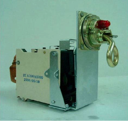


CSP Circuit Breaker - Single Phase
The CSP protection concept is generally applied to Single phase transformers up to 200kVA (where a 120/240 and 240/480 volts low voltage winding is typical). The CSP concept is applied to systems where the low voltage of the transformer might be in the range of 400 to 480 volts.
P&A offers four different oil circuit breaker designs: the type LR breakers, generally applied from 10KVA through 25KVA ; the type SQR breakers, generally applied from 37.5kVA through 50kVA ; the type LQR breaker which is generally applied from 75kVA through 100kVA ; and type HQR breaker generally applied to 167kVA and 200kVA transformers. The rated current of the transformer determines which breaker family is appropriate. For values of low voltage outside of the 120/240 V class the corresponding KVA range of transformer sizes are in table 3&4
The CSP breaker is connected to the transformer between the low voltage winding and the secondary bushing’s internal terminals (please refer to the schematic diagram shown in Figure 1). The connections are made so that the secondary load current flows through both the breaker bimetal and contact. This is necessary to properly monitor the secondary transformer current and load levels.
The breaker is available with two auxiliary features : a signal light contact and an emergency control setting. The signal light contact is connected into the signal light circuit and is used to provide an early warning of transformer overload. The signal light operates on approximately 4 to 6 volts (14 volts optional), picked up by an auxiliary winding of consisting of one or two turns through the core. (The signal light contact is an optional feature of the circuit breaker and should be specified, if desired).
The emergency control mechanism is a mechanical linkage inside the breaker which moves the breaker to a higher calibration temperature setting when placed into the emergency position. (This is also an optional feature and should be specified, if desired)
